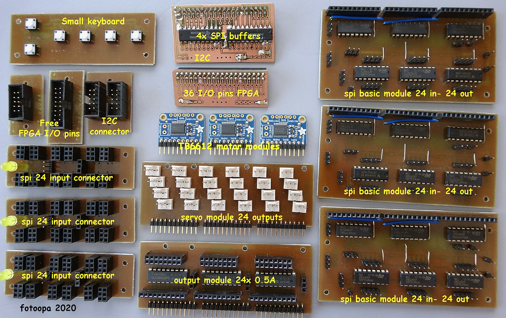
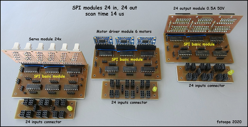
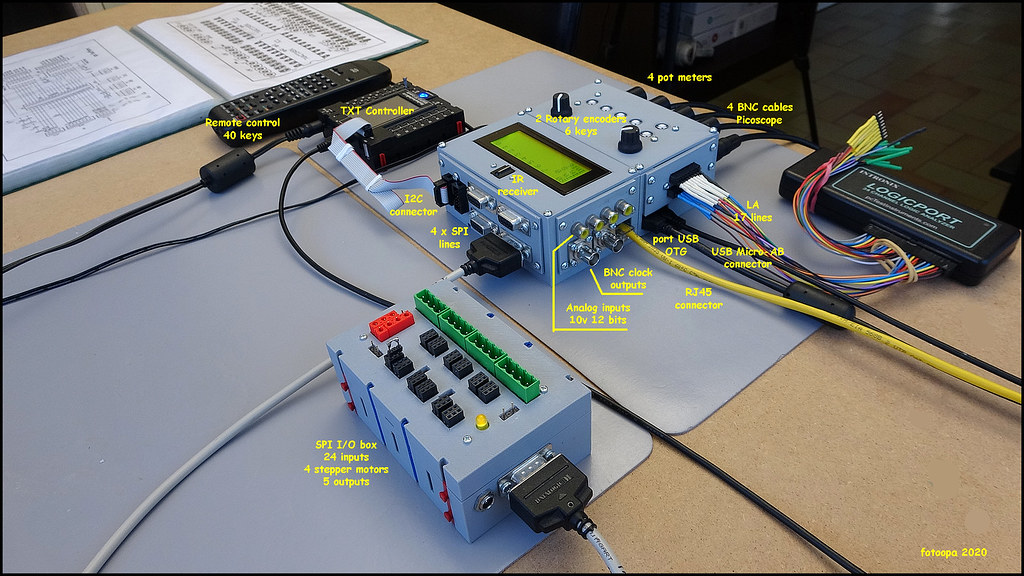
Testing of the spi motor module.
The module contains 3 TB6612 motor drivers to control 6 motors. Full control of the motors is done in the De0 nano soc module. The commands are sent by the TXT controller over the I2C connection. The motors get support for quadrature encoders, min and max switch, home switch and calibration. The position counter is kept in the FPGA module. The TXT only specifies the soll, Ist, speed, braking zone and braking speed. For this reason, the TXT doesn't have a lot of work to handle a lot of motors. I now have 2 spi modules each for 6 motors. If necessary I can add more modules as I have 5 spi lines at my disposal.
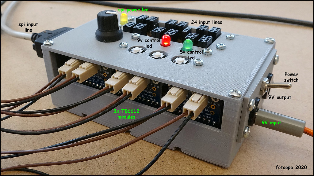
The spi module has an external input for the 9V power supply. A second connector makes it possible to forward the power supply to the next module. An extra switch can turn off the 9V in the module.
Each motor can work in one of the 5 modes. These are:
mode 0 :
Single start, stop, dir and speed.
mode1 :
Position control with 1 motor impulse encoder, counting on the positive edge.
mode 2 :
Position control with 1 motor impulse encoder, counting on the negative edge.
mode 3 :
Position control with 1 motor impulse encoder, counting on both edges.
mode 4 :
Position control with motor quadrature encoders.
Mode 1 to mode 4 also have a brake zone and a brake speed. All parameters are given by the TXT.
The module contains 2 extra leds. When the external voltage is 5V only 1 led is lit. If the external power supply is higher than 6.5V the 2 leds are lit.

HD picture Flickr:
https://www.flickr.com/photos/fotoopa_hs/50401530377
HD picture Flickr:
https://www.flickr.com/photos/fotoopa_hs/50401372836
Frans.