Hell Frans,
my best wishes to your marriage anniversary!
When you would like to come back to the topic: I am wondering about your measurements taken.
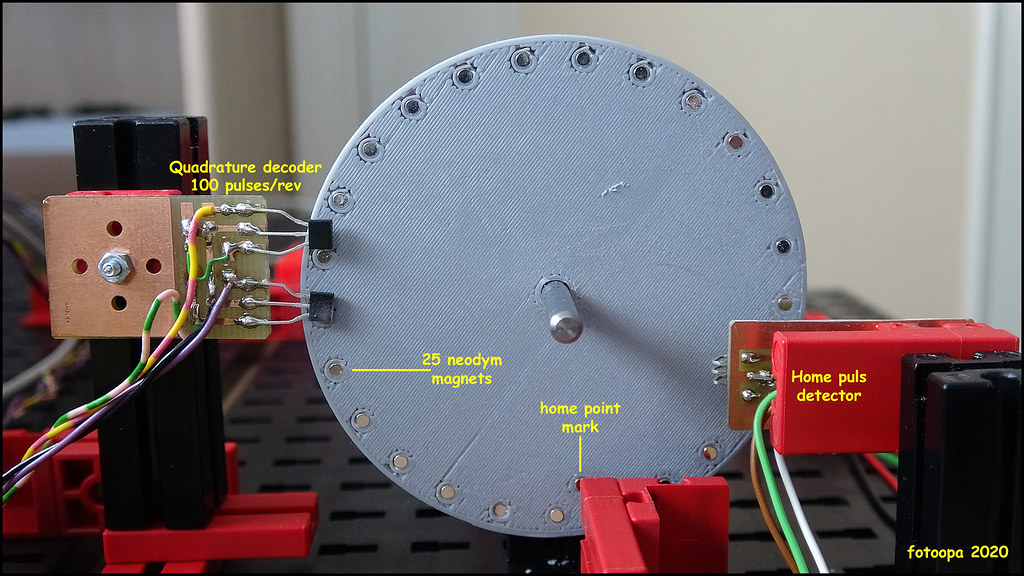
First I understand you have a disc with 25 "teeth" and use a quadrature sensor to get 100 counts
per output shaft rotation.
I miss a little your figure of "teeth" on the input shaft. How many do we have here?
Next is your Verilog code:
Code: Alles auswählen
quad_pos_high <= motor_pos/1000;
quad_pos_low <= motor_pos-(quad_pos_high*1000);
edge_pos_high <= edge_pos/1000;
edge_pos_low <= edge_pos-(edge_pos_high*1000);
The calculations work, indeed. But doing these divisions and multiplications might infer lots of FPGA ressources and cause timing violations.
To split up a wide vector of bits into narrower portions (or vice versa) I prefer something like this usually:
Code: Alles auswählen
input   [19:0] a;       // 20-bit input
outputL [9:0] resultL;  // 10-bit output
outputH [9:0] resultH;  // 10-bit output
assign resultL = a[9:0];
assign resultH = a[19:10];
Of ocurse, this also works with
reg-type. The pieces then you convert back on the receiver side by calculating
But now to the biggest issue. Your two impulse counters are synchronized by mechanics. At one certain position of the output shaft you receive the conincidence of the exact fraction. Everywhere in between you suffer from the fact that you receive different counts of edges giving a variation in the quotient! I will try an example:
Output shaft gives 100 counts per its own revolution. Input shaft gives 6 pulses (3 rising, 3 falling edges) per its own revolution. With a gear ratio of 2/25 (output/input) you get 3 * 25 = 75 pulses on the input shaft for 100 pulses of the output shaft. You might get something like this:
Code: Alles auswählen
output    _____       _____       _____
I      __/     \_____/     \_____/
         :   _____   :   _____   :   __
Q      _____/     \_____/     \_____/
       0 :1 :2 :3 :4 :5 :6 :7 :8 :9 :10
         |<-  2/25 Revolutions ->|

       0 1  1  2  3  3  4  5  6  7   7
       - -  -  -  -  -  -  -  -  -  --
       0 1  2  3  4  5  6  7  8  9  10

input     ___     ___     ___     ___
       __/   \___/   \___/   \___/   \_
       0 :1  :2  :3  :4  :5  :6  :7  :8
         |<--  1 Revolution   -->|
The gear reduction thus can get calculated by (counts on input shaft / counts on output shaft) * (counts per 1 rev of output / counts per 1 rev of input) and for the example this is (counts on input shaft / counts on output shaft) * 100 / 6). Now take the momentary quotients from above and calculate for each. You will get the sequence of results:
Code: Alles auswählen
1/1 = 16,6667
1/2 =  8,3333
2/3 = 11,1111
3/4 = 12,5000
3/5 = 10,0000
4/6 = 11,1111
5/7 = 11,9048
6/8 = 12,5000
7/9 = 12,9630
7/10= 11,6667
Now take a look on the error and then you might find that your uncertainty always is a certain fraction of the output shaft revolution. You might expect the error to be less than 1 % since your resolution is 100 pulses per revolution (output). But please calculate the error of the momentary results and you see the issue yourself. With 10000 revolutions of the output shaft you receive 125000 revolutions of the example input shaft (250000 with the "old" encoder). Based on your measurement setup you might get the residual error smaller and smaller, but you never will reach 0.
Do you gate both counters and stop counting input pulses when the output gives its 1000000th pulse?
And one more thing: The motor itself might produce erratic pulses due the commutator sparks. Eventually those little beasts give you some extra hazzle with counting the pulses?
The ultimate method to determine a gear reduction ratio indeed is counting the teeth - like hamlet already did.
Regards
H.A.R.R.Y.