The original thread is in English. I’ll chime in here with something that hopefully isn’t too far off-topic...
I’m comparing the (historical) I2C pinout and voltages of the TX, TXT, and, for example, the ftExpander with the pinout (or “connector orientation”) of the TXT4.0. I’m doing this because I want to create a 6-pin (2x3) Dupont connector for this that’s as practical as possible for my current development project. Of course, there’s the choice between 5 volts (TX and ftDuino) and/or 3.3 volts (TXT and TXT 4.0), but there’s also something else that stands out to me and confuses me.

On the flat cable Dupont connectors, the odd-numbered pins (1, 3, and 5) are on the side of the notch that prevents reverse insertion. This was always (for TX, ftDuino, and TXT) the GROUND. So GROUND is on pin 1 and the + (5 or 3.3 volts) is on pin 2. See the pinout for the TX, ftDuino, and TXT in the images below. This actually resulted in the counterintuitive phenomenon where the first wire of the flat cable, marked in red, on pin 1 was actually ground instead of the more intuitive positive terminal.
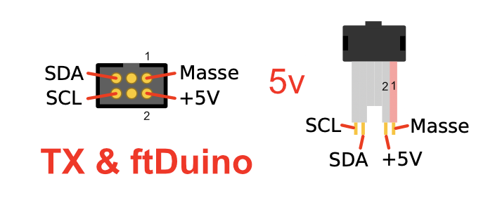
- TX-ftDuino-5v.png (46.17 KiB) 6110 mal betrachtet
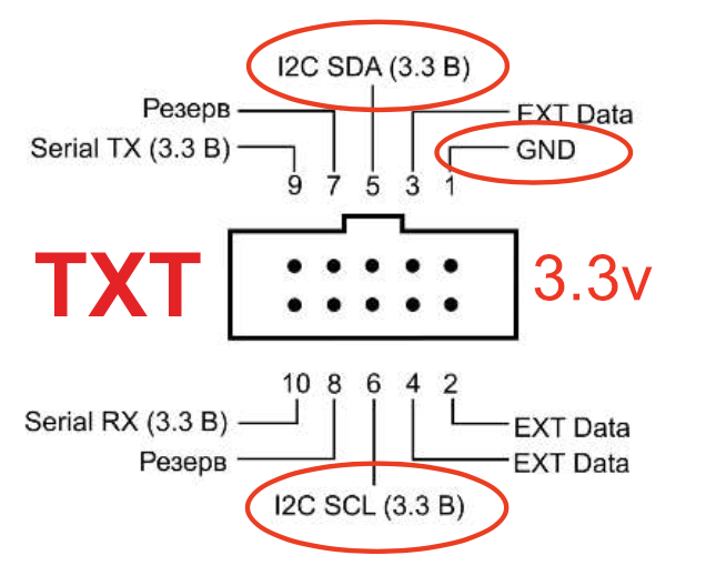
- TXT-Pinout-3.3v.png (138.7 KiB) 6110 mal betrachtet
However, the connector on the TXT 4.0 appears to have been flipped along its longitudinal axis. Pin 1 (the red, marked, wire of the flat cable) is now
actually the positive terminal. This means that SDA and SCL have also been
reversed!

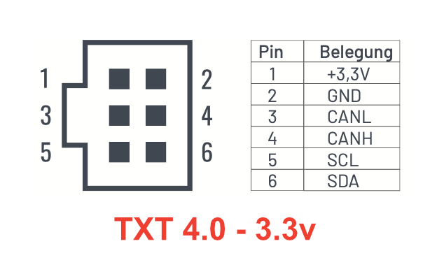
- TXT4.0-Pinout-3.3v.png (32.25 KiB) 6110 mal betrachtet
Am I misunderstanding something, or is it true that sensors cables or, for example, cables to the ftExtender—which used to be compatible with the TX, ftDuino, and TXT—can no longer be connected to the TXT 4.0 without further ado? And that anyone who wants to use the ftExtender with the TXT 4.0, for instance, needs a (mirroring) converter for this?
In Richard’s photo (
https://forum.ftcommunity.de/viewtopic.php?f=8&t=9650), I think I see something like that; I’ll ask him the question as well because I’m now unsure which connectors—and consequently which pinout—I should choose.
To avoid confusion when connecting, I’m now leaning toward choosing the same connectors I’ve already used on previous modules (including my ‘Zauberling’). After some research, I opted for the (at least in terms of pinout) compatible ‘Grove/Seeed’ 4-pin JST-PH connectors. Since they take up relatively little space, they could then be used directly for 5 and 3.3 volts, respectively.
Finally... I see there’s a lot of ftExtender expertise here (I don’t own one myself, and I see that the documentation was last updated in 2018, before the TXT 4.0 was released). I’ve gone over the website, GitHub, manual, and the article in ft:pedia 2/2018 again, but I still don’t understand what the three “shields” in the 14-pin connectors are for. Is this some kind of block to prevent certain connectors from being plugged in? It’s not a big deal, but maybe someone knows why this is in the product photo and whether it serves a practical purpose. Just curious...

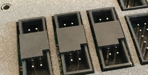
- connector-plates.png (247.54 KiB) 6110 mal betrachtet


 )
)