Hello Rei,
Thank you for your note.
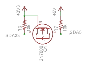
Youré right, the wiring diagram is missing the power supply and logic level converter.
I have removed the video.
Regards
Dirk
ROBO Pro 4.2.3 + neue Firmeware TXT mit I2C verfügbar
Forumsregeln
Bitte beachte die Forumsregeln!
Bitte beachte die Forumsregeln!
Re: ROBO Pro 4.2.3 + neue Firmeware TXT mit I2C verfügbar
Hallo Dirk:
You're welcome!
Maybe publishing the schematics in the next release of ft:pedia would help many ft fans!
You're welcome!
Maybe publishing the schematics in the next release of ft:pedia would help many ft fans!
Re: ROBO Pro 4.2.3 + neue Firmeware TXT mit I2C verfügbar
Hello Rei,
many thanks for our information with the I2C port and your proposal for the connection with some sensors to the TXT.
For the connection with the levels shifter, I have a question. Why is the power pin 5V from the level shifter not connected with the power supply 5V?
I mean, this must be neccessary.
kind regards Karsten
Re: ROBO Pro 4.2.3 + neue Firmeware TXT mit I2C verfügbar
Hello Karsten:
I'm not sure to understand your question. The +5 V is indeed connected, using the labels.
Same applies for + 9 V, + 5 V, + 3,3 V, GROUND, SCL5, SDA5, SCL33, SDA33.
I'm not sure to understand your question. The +5 V is indeed connected, using the labels.
Same applies for + 9 V, + 5 V, + 3,3 V, GROUND, SCL5, SDA5, SCL33, SDA33.
Re: ROBO Pro 4.2.3 + neue Firmeware TXT mit I2C verfügbar
Hello Rei,
sorry, that my question is not clear.
You have connected on the level shifter BV side GND, SCL, SDA and 3,3V on the AV side SCL and SDA. I mean, you have also to connect 5V on the AV side from the level shifter.
kind regards Karsten
sorry, that my question is not clear.
You have connected on the level shifter BV side GND, SCL, SDA and 3,3V on the AV side SCL and SDA. I mean, you have also to connect 5V on the AV side from the level shifter.
kind regards Karsten
Re: ROBO Pro 4.2.3 + neue Firmeware TXT mit I2C verfügbar
What AV and BV stand for?
Both +3,3 V and 5 V are connected to the voltage regulators.
Connection to GOUND is not required. See I²C Logic Level Converter.
Feel free to add arrows to the schematics to identify your question.
Both +3,3 V and 5 V are connected to the voltage regulators.
Connection to GOUND is not required. See I²C Logic Level Converter.
Feel free to add arrows to the schematics to identify your question.
Re: ROBO Pro 4.2.3 + neue Firmeware TXT mit I2C verfügbar
Hello Rei,
this is mistake from my side. Your diagramms are correct. Sorry!
I thought, that the you tube video (https://www.youtube.com/watch?v=COTq-0OeWuI) is from your side. In this video "Robo TXT Controller I²C Conrad SAA 1064 ansteuern" is a wiring diagram ("Schaltschema") with a level shifter connected BV side GND, SCL, SDA and 3,3V and on the AV side is only SCL and SDA connected. And here I miss the 5V power.
kind regards Karsten
Re: ROBO Pro 4.2.3 + neue Firmeware TXT mit I2C verfügbar
Hello Karsten:
No problem! Glad to have found a solution.
I'm not the author of the video you're mentioning.
Actually, it prompted me to post my initial comment on this thread.
No problem! Glad to have found a solution.
I'm not the author of the video you're mentioning.
Actually, it prompted me to post my initial comment on this thread.
Re: ROBO Pro 4.2.3 + neue Firmeware TXT mit I2C verfügbar
Hallo TXT-i2c Fans,
Mit großem Interesse habe ich die "Pin 9 3.3V-Serial-TX"-Diskussion verfolgt. Ich hatte auch schon im "Robo TX + I2C-Kamera Objekterkennung"-Thema meine Hoffnung/Skepsis diesbezüglich kundgetan. Dass der TXT keinen 3.3V-Ausgang zur Verfügung stellt, ist ziemlich blöde.
Trotzdem ist die Versuchung, den 3.3V-Serial-TX-Ausgang als Spannungsquelle - zumindest als Versorgungs/Referenzspannung für einen Level-Shifter - zu missbrauchen, einfach zu groß gewesen, und ich möchte die E-Technik-Experten unter Euch um Absolution für folgenden Aufbau bitten: Kann man das so machen, auch wenn's eigentlich kacke ist?
Versuchsaufbau:
Der TXT tickert in den ersten 18s nach Power On über den Serial-TX den U-Boot- und Linux-Startup-Log raus, danach liegen 3.3V High Pegel an. (Was da so "fundamental falsch" mit dem i2c-EEPROM läuft, weiß ich nicht. Die Meldung kommt auch, wenn der TXT bis auf die Serielle nackt ist):
 (BBCode scheint die OneDrive-KauderwelschLinks nicht zu mögen. Bitte über Rechts-Klick-Kontext-Menü öffnen: "Grafik anzeigen" oder "In neuem Tab öffnen")
i2c-Kommunikation:
Läuft problemlos!
Im Bild sieht man den Spannungsverlauf am 3.3V TXT Serial-TX (Channel 1) und das i2c-Clock-Signal (Channel 2).
Beim 3.3V Signal sind drei Spannungs-Niveaus zu erkennen, die sich wahrscheinlich aus der Belastung des 3.3V-Ser-TX über die 4K7 Pullups ergeben, wenn die i2c Data- und/oder die Clock-Leitung auf Null gezogen wird. Die Spannung bleibt aber immer oberhalb von 3V.
 (BBCode scheint die OneDrive-KauderwelschLinks nicht zu mögen. Bitte über Rechts-Klick-Kontext-Menü öffnen: "Grafik anzeigen" oder "In neuem Tab öffnen")
Für mich sieht das einigermaßen OK aus. Oder?
Interessant ist noch, dass der TXT trotz angeforderter 400kHz Clock lediglich mit 100kHz auf dem Bus unterwegs ist.
Beste Grüße,
Helmut
Mit großem Interesse habe ich die "Pin 9 3.3V-Serial-TX"-Diskussion verfolgt. Ich hatte auch schon im "Robo TX + I2C-Kamera Objekterkennung"-Thema meine Hoffnung/Skepsis diesbezüglich kundgetan. Dass der TXT keinen 3.3V-Ausgang zur Verfügung stellt, ist ziemlich blöde.
Trotzdem ist die Versuchung, den 3.3V-Serial-TX-Ausgang als Spannungsquelle - zumindest als Versorgungs/Referenzspannung für einen Level-Shifter - zu missbrauchen, einfach zu groß gewesen, und ich möchte die E-Technik-Experten unter Euch um Absolution für folgenden Aufbau bitten: Kann man das so machen, auch wenn's eigentlich kacke ist?
Versuchsaufbau:
- TXT
- 4.2.3-Firmware
- über 9V ft-Netzteil versorgt
- Führt offline den Pixy-CMU5 Cam Treiber aus
- Pixy-CMU5 Camera
- über den (6-10)V Power Eingang vom TXT versorgt
- mal mit, mal ohne USB-Verbindung zum PC
- schickt über i2c die Positions-, Farb-ID- und Größendaten zum TXT.
- Die i2c-Kommunikation der beiden erfolgt über den sehr kompakten und preiswerten Knick-Knack-Aus-Eins-Mach-Zwei Level-Shifter
- Er folgt wie Reis Design-Vorschlag dem Philips-Referenzdesign (BSS138 N-channel FET + 4K7 Pullups)
- Die 5V-Referenz liefert die Pixy-Cam über Pin 2 (5V in/out) ihres I/O-Connectors
- Die 3.3V-Referenz liefert der böse 3.3V-Serial-TX des TXT
- => Das Charmante an diesem Aufbau ist, dass man außer dem klitzekleinen Levelshifter keine weiteren Breakout-Boards zur Spanungsversorgung braucht.
- Zusätzlich hängt am Serial-TX des TXT noch folgender USB-Serial-Adapter und mein liebgewonnenes Billig-China-Scope.
Der TXT tickert in den ersten 18s nach Power On über den Serial-TX den U-Boot- und Linux-Startup-Log raus, danach liegen 3.3V High Pegel an. (Was da so "fundamental falsch" mit dem i2c-EEPROM läuft, weiß ich nicht. Die Meldung kommt auch, wenn der TXT bis auf die Serielle nackt ist):
Code: Alles auswählen
U-Boot SPL 2013.10 (Jul 04 2015 - 08:30:17)
>>> I2C0 On
Could not probe the EEPROM; something fundamentally wrong on the I2C bus.
Could not get board ID.
>>> setup_dplls vor do_setup_dpll
>>> setup_dplls nach do_setup_dpll
Could not probe the EEPROM; something fundamentally wrong on the I2C bus.
Could not get board ID.
>>> Setting MUX Start
>>> Setting MUX End
Could not probe the EEPROM; something fundamentally wrong on the I2C bus.
Could not get board ID.
>>>Start TXT-Mode - V2
LCD-Init_4:
Could not probe the EEPROM; something fundamentally wrong on the I2C bus.
Could not get board ID.
---> MPU 1000 VDD 61


U-Boot 2013.10 (Jul 04 2015 - 08:30:17)

I2C:   ready
DRAM:  256 MiB
NAND:  128 MiB
MMC:   OMAP SD/MMC: 0, OMAP SD/MMC: 1
Could not probe the EEPROM; something fundamentally wrong on the I2C bus.
Could not get board ID.
Net:   usb_ether

NAND read: device 0 offset 0x700000, size 0x40000
 262144 bytes read: OK
CopyToLcd
LCD Command called
Hit ENTER key to stop autoboot:  0
gpio: pin 97 (gpio 97) value is 0
gpio: pin 98 (gpio 98) value is 0

NAND read: device 0 offset 0x200000, size 0x500000
 5242880 bytes read: OK

NAND read: device 0 offset 0x80000, size 0x40000
 262144 bytes read: OK
## Booting kernel from Legacy Image at 80200000 ...
   Image Name:   Linux-3.16.1
   Image Type:   ARM Linux Kernel Image (uncompressed)
   Data Size:    4725040 Bytes = 4.5 MiB
   Load Address: 80008000
   Entry Point:  80008000
   Verifying Checksum ... OK
## Flattened Device Tree blob at 80f00000
   Booting using the fdt blob at 0x80f00000
   Loading Kernel Image ... OK
   Loading Device Tree to 8f309000, end 8f3140ed ... OK

Starting kernel ...

[    0.822551] mtdoops: mtd device (mtddev=name/number) must be supplied
[    0.876049] omap_hsmmc 48060000.mmc: unable to get vmmc regulator -517
[    0.925293] omap_voltage_late_init: Voltage driver support not added
[    0.934719] cpu cpu0: cpu0 regulator not ready, retry

fbv - The Framebuffer Viewer
/etc/ft-logo.bmp
240 x 320


UIM SYSFS Node Found at /sys/./devices/kim/install
Starting uim-sysfs daemon.
Populating /dev using udev: done
Initializing random number generator... done.
Starting system message bus: done
Starting network...
ip: can't find device 'usb0'
ip: SIOCGIFFLAGS: No such device
ip: SIOCGIFFLAGS: No such device
Starting sshd: OK
/etc/init.d/S93-am335x-pm-firmware-load: line 4: can't create /sys/devices/ocp.2/44d00000.wkup_m3/firmware/am335x-pm-firmware.bin/loading: nonexistent directory
/etc/init.d/S93-am335x-pm-firmware-load: line 5: can't create /sys/devices/ocp.2/44d00000.wkup_m3/firmware/am335x-pm-firmware.bin/data: nonexistent directory
/etc/init.d/S93-am335x-pm-firmware-load: line 6: can't create /sys/devices/ocp.2/44d00000.wkup_m3/firmware/am335x-pm-firmware.bin/loading: nonexistent directory
Starting bluetooth NAP...
Starting usb g_ether network...
ifdown: interface usb0 not configured
Starting dhcpd...
rm: can't remove '/tmp/dhcp_leases.list': No such file or directory
Internet Systems Consortium DHCP Server 4.1-ESV-R9
Copyright 2004-2014 Internet Systems Consortium.
All rights reserved.
For info, please visit https://www.isc.org/software/dhcp/
Wrote 0 leases to leases file.
Listening on LPF/usb0/00:54:58:54:ff:01/192.168.7.0/30
Sending on   LPF/usb0/00:54:58:54:ff:01/192.168.7.0/30
Listening on LPF/pan0/c6:f4:15:21:7d:e9/192.168.9.0/24
Sending on   LPF/pan0/c6:f4:15:21:7d:e9/192.168.9.0/24
Sending on   Socket/fallback/fallback-net


FT-txt: FT-txt /dev/ttyO0

FT-txt login:
i2c-Kommunikation:
Läuft problemlos!
Im Bild sieht man den Spannungsverlauf am 3.3V TXT Serial-TX (Channel 1) und das i2c-Clock-Signal (Channel 2).
Beim 3.3V Signal sind drei Spannungs-Niveaus zu erkennen, die sich wahrscheinlich aus der Belastung des 3.3V-Ser-TX über die 4K7 Pullups ergeben, wenn die i2c Data- und/oder die Clock-Leitung auf Null gezogen wird. Die Spannung bleibt aber immer oberhalb von 3V.
Für mich sieht das einigermaßen OK aus. Oder?
Interessant ist noch, dass der TXT trotz angeforderter 400kHz Clock lediglich mit 100kHz auf dem Bus unterwegs ist.
Beste Grüße,
Helmut
Re: ROBO Pro 4.2.3 + neue Firmeware TXT mit I2C verfügbar
The problem is twofold.
Now, getting 3.3 V for reference can be done very easily from 5 V through a voltage divider with resistors. Find here explanations and a handy calculator.
- Using Serial-TX as 3.3 V power source may interfere with the serial signals used for debugging.
- No one can recommend using the Serial-TX as 3.3 V power source because of legal consequences. I sincerely doubt that fischertechnik would accept exchanging a defective Robotics TXT because of this non official usage. IMHO, this voids the warranty.
Now, getting 3.3 V for reference can be done very easily from 5 V through a voltage divider with resistors. Find here explanations and a handy calculator.
Re: ROBO Pro 4.2.3 + neue Firmeware TXT mit I2C verfügbar
Hello Rei,
Thanks for your advice. If I brick my TXT by trying undocumented stuff, it's clearly my responsibility. Asking for a warranty covered repair or replacement in that case would be rather mean.
But my question wasn't about warranty. I try to rephrase it: "Does a 3.3V/(4K7||4K7)~1.4mA current through the two 4K7 pullup resistors of the level shifter causing a ~200mV-250mV drop of the 3.3V high level of the evil Pin 9 already look like an unreasonable stress to this output? Is the gate switching current of the FET negligible?" (I wouldn't hold anybody liable for his answer)
That serial logs sent out by the TXT might interfere with the i2c communication is obvious. Thus I have posted the power-on sequence above.
Generating the 3.3V using a simple voltage divider would work out nicely, if the load would be constant. But unfortunately it's not. Thus it has to be rather low-resistance compared to the 4K7||4K7 pullup resistors, potentially making it a little heater powered by the 5V source.
Best Regards,
Helmut
Re: ROBO Pro 4.2.3 + neue Firmeware TXT mit I2C verfügbar
We'd need to have a look at the schematics and know how the TX is wired. So the answer is no.hamlet hat geschrieben: "Does a 3.3V/(4K7||4K7)~1.4mA current through the two 4K7 pullup resistors of the level shifter causing a ~200mV-250mV drop of the 3.3V high level of the evil Pin 9 already look like an unreasonable stress to this output? Is the gate switching current of the FET negligible?"
The I²C devices need to be powered. Why not to use one of the power rail for the +3.3 V reference needed by the logic level converter?
Two recommendations:
- Avoid connecting anything except a 3.3V FTDI driver to the TX and RX pins of the Serial port.
- Ask fischertechnik on the Kontakt mis fischertechnik thread for an official answer.