Using lego devices with the TXT

Fussballroboter, Autofabrik...
Modellideas &- presentation - Soccerrobot, Carfactory...
Forumsregeln
Bitte beachte die Forumsregeln!
Antworten
fotoopa
Beiträge: 315
Registriert: 05 Okt 2017, 11:44
Wohnort: Belgie
Kontaktdaten:

Using lego devices with the TXT

Beitrag von fotoopa » 23 Apr 2024, 11:12

Using lego devices with the TXT.

Why would you do this? FT has nice motors and devices too, right?

Ah, yes but unfortunately FT does not have a 9V motor with built-in quadrature encoder. They do have an encoder motor with 1 pulse signal. Their PCB did foresee to put 2 hall decoder on it but apparently they wanted to save money. So we cannot make a real quadrature decoder anymore. With 1 signal line you are never 100% sure on correct pulse count and direction of the motor.

Lego does have a quadrature decoder built in and it is also absolute. But they also have another 32bit counter built in. So the absolute position and the relative 32bit counter are available at any time. The motor is not even more expensive either.

It is so far, all my Lego devices are now controlled by my Cyclone10 LP FPGA. All 8 Port inputs work with auto detection of the Lego device. All data can be read out and is available for the TXT controller. Through the TXT software I can now read out and control all the device.
This project is still in full development. Almost all available IO pins have been used. With the remote control of an old DVD player I still have 40 keys available. This is how I select the 4 pages of the LCD 4x20 char display.

Bild
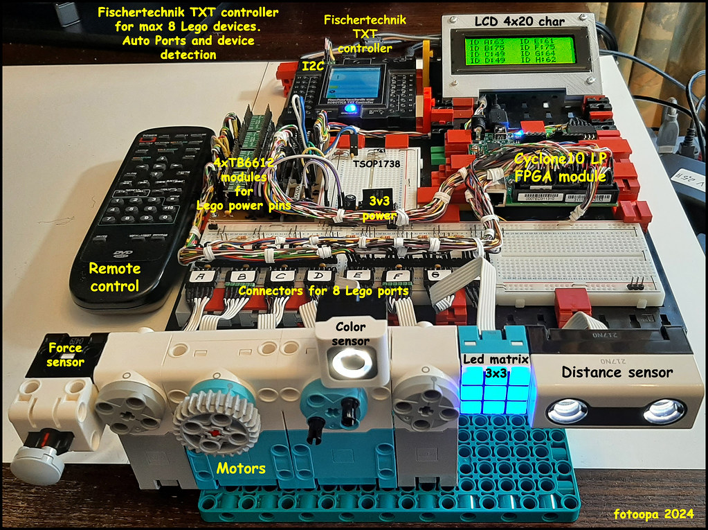
Fischertechnik + Lego + FPGA by Frans, on Flickr

The Lego motors have a built-in absolute encoder and also a 32bit relative position counter built in. One revolution of the motor corresponds to 360 pulses. These motors in particular have many advantages over the Fischertechnik motors. FT has no built-in counter and the encoder is only 1 channel so true quadrature decoding with an FT motor is not possible. Lego is an excellent replacement for this.

The TXT may also control power pins 1 and 2. The position is available via I2C. With the PC you can control up to 4 motors with the TXT software.
However, if you want to control up to 8 motors with the FPGA then it is also possible. Then the TXT motor outputs are not connected but the power pins are controlled with the TB6612 modules. Thus, the TXT remains fully available for the normal FT modules. The nice thing is that all readout can now be done on the PC. At the same time, results can be displayed on the LCD screen. All decoded device IDs are on page1 of the LCD display and you can see which Lego device is active.

I am now going to make extension cables for the Lego devices. This can be done with twisted pair cable of 3x2x0.14 or 4x2x0.14 With twisted pair you can maintain better signal transmission for the 2 serial lines. If you use 4x2x0.14 then you have more diameter for the power pins of the motors. These cables are quite thin and flexible making them very movable.

To accomplish this, I had to study the Lego protocol. I also gained a lot of info through Pybricks. Thanks to Pybricks software (Python and blocks) I was able to make a lot of measurements. I use also a Picoscope 3206D MSO 200Mhz with 16 channels logic analyzer. Thanks to this scope, you can make very deep analyses. The project is not yet finished; there is still much room for optimization. This project allows me to reuse my old TXT controller.

Frans.

kräml
Beiträge: 305
Registriert: 14 Aug 2020, 06:47

Re: Using lego devices with the TXT

Beitrag von kräml » 23 Apr 2024, 11:27

Wow, great project. Just the way I like it. FPGA as a mediator between the worlds, here FT with Lego. Great! I'm currently working on the MAX1000. But I hadn't thought of this idea yet. Thanks for the information.

Kraeml

fotoopa
Beiträge: 315
Registriert: 05 Okt 2017, 11:44
Wohnort: Belgie
Kontaktdaten:

Re: Using lego devices with the TXT

Beitrag von fotoopa » 23 Apr 2024, 13:07

It doesn't matter so much which board you take. As soon as you have enough IO pins, a PLL and minimum 20K LE you will be fine. I use verilog code, you can use it like that from one board to another. Just redefine the IO in the list.

Here are the Quartus compiler output data:
Flow StatusSuccessful - Mon Apr 22 19:56:14 2024
Quartus Prime Version22.1std.2 Build 922 07/20/2023 SC Lite Edition
Revision Namecycl10_lcd
Top-level Entity Namecycl10_lcd
FamilyCyclone 10 LP
Device10CL025YU256I7G
Timing Models Final
Total logic elements 11,163 / 24,624 ( 45 % )
Total registers 6182
Total pins 134 / 151 ( 89 % )
Total virtual pins 0
Total memory bits 1,152 / 608,256 ( < 1 % )
Embedded Multiplier 9-bit elements0 / 132 ( 0 % )
Total PLLs 1 / 4 ( 25 % )

As you can see, there is still plenty of room to program additional functions. Now the chip is 45% full.

I have a whole range of FPGA boards. One slightly more expensive than the Cyclone10 LP is the older DE0-nano. That one has a huge number of IO pins. There is plenty of choice.
Frans.

vleeuwen
Beiträge: 1609
Registriert: 31 Okt 2010, 22:23
Wohnort: Enschede (NL)
Kontaktdaten:

Re: Using lego devices with the TXT

Beitrag von vleeuwen » 23 Apr 2024, 13:32

The lack of a rotary (quadrature) decoder functionality on the TXT4.0 (and the TXT and TX-C) is a loss.
The Incremental decoder sometimes causes problems in various applications if there is loopback.
However, if the mechanical transmission is blocking, for example with a worm transmission, an incremental encoder in combination with software direction processing is sufficient for 100%.
A good rotary encoder is quite expensive. The 200 p/r quadrature encoder from Sparkfun with a 4mm shaft can be used in combination with fischertechnik. This in combination with an I2C based decoder.

See also: https://www.sparkfun.com/products/10932
https://hades.mech.northwestern.edu/ind ... re_Counter
https://www.globalspec.com/industrial-d ... nter_chips
https://hades.mech.northwestern.edu/ind ... re_Counter

Microchip hardware decoder function on the dsPIC33F serie, PIC32 serie, dsPIC33/PIC24 serie (Quadrature Encoder Interface (QEI))
https://ww1.microchip.com/downloads/en/ ... 70208A.pdf
https://ww1.microchip.com/downloads/en/ ... 01346A.pdf
https://ww1.microchip.com/downloads/en/ ... 00601c.pdf
software enigineer/teacher/advisor
Google translate
http://tescaweb.nl/Carel/?p=713

fotoopa
Beiträge: 315
Registriert: 05 Okt 2017, 11:44
Wohnort: Belgie
Kontaktdaten:

Re: Using lego devices with the TXT

Beitrag von fotoopa » 10 Jul 2024, 18:48

Just for fun, I have now used a DE10 nano board to control up to 8 lego devices. This board has a larger FPGA chip 5CSBA6U23I7 (110k LE's) and has more available I/O pins. The Cyclone10 version was already more than 73% full.
The setup is the same. I use the TXT as an interface to windows11. This allows me to access all registers of the FPGA via the I2C connection.
Up to 8 different Lego devices can be connected. They are detected automatically. The necessary power pins are thus automatically assigned.
The chip contains 2 parts, FPGA and HPS part for which a Linux version is provided. I do not use the HPS part. Because of this, the chip also requires less power and has a lower temperature. The FPGA is programmed in verilog.

BildDE10-nano + up to 8 Lego devices by Frans, on Flickr

On the breadboard I also connected the 8ch ADC. The 8 channels are shown on Page4 of the LCD display. The ADCs have a resolution of 12bit (0..4095). The pages of the LCD display are selected via the remote control unit. There, up to 40 keys are available to assign different functions. Below the LCD display are 2 dc-dc converters from 9V to 3.3 and 5V. These provide all voltages for the entire setup.
The DE10-Nano + LCD display + TXT currently consume 847mA on the 9V.

There is still room to add 1 more breadboard. This has also arrived and has now been mounted (not on the current photo).
Of the Arduino interface connectors, I only have 2 pins in use, this one for the I2C with the TXT. On the connector on the LCD side there are another 26 free I/O pins available. Many more extensions are still possible.
The TXT is primarily used as an interface between the FPGA and Windows 11. Within the FPGA, 512x8bit registers are available for reading and writing. With the Robopro program from Fischertechnik I can use this to graphically exchange all data in real time on the screen. For this I use 2 UHD 32 inch screens 3840x2160 pixels.

To control the motors I can either use the TXT but limited to 4 motors or via internal FPGA modules but up to 8 motors. If you use the TXT controller for the motors then you have to provide the motor control there. If you do that via the FPGA routines then you have to make the necessary verilog modules yourself. I am now going to modify old existing verilog routines. The Lego motors have an internal encoder that can display the position of the motors. To control the motors I use an old made module with the TB6612 drivers.
I now use a single 9V power supply. For this I used the programmable lab power supply from Korad the KA3005PS. The advantage here is that additional protections are possible. This is necessary because during the tests I had short-circuited with the GND of the Picoscope. As a result, the power supply just went into overcurrent and turned off.

Frans.

Antworten