The magic ball track.
Forumsregeln
Bitte beachte die Forumsregeln!
The magic ball track.
This ball track has something magical about it. The balls go gently up and then back down. The total height of the track is 720mm. Only a TXT Controller from Fischertechnik is needed. The assembly contains several thousand blocks. A few special blocks are 3D printed. Programmed with Robopro.
A short video:
The magic ball track. by Frans, on Flickr
A short video:
The magic ball track. by Frans, on Flickr
- steffalk
- ft:pedia-Herausgeber
- Beiträge: 1794
- Registriert: 01 Nov 2010, 16:41
- Wohnort: Karlsruhe
- Kontaktdaten:
Re: The magic ball track.
Hello Fotoopa,
what a *fabulous* idea! Just wonderful and a fun to watch!
Best Regards,
Stefan
what a *fabulous* idea! Just wonderful and a fun to watch!
Best Regards,
Stefan
- ThanksForTheFish
- Beiträge: 599
- Registriert: 03 Nov 2010, 21:00
- Wohnort: 30900 Wedemark
Re: The magic ball track.
Dear fotoopa,
this is 'frans'tastic!
I really like your ideas.
best regards, Ralf
this is 'frans'tastic!
I really like your ideas.
best regards, Ralf
Nordconvention am 20. April 2024 im Schulzentrum Mellendorf in 30900 Wedemark
Re: The magic ball track.
Dear fotoopa,
thanks for sharing this mesmerizing art work!
It reminds me to the Marble Madness level "Everything you know is wrong".
And i would assume that there is also a juicy FPGA behind the scenes.
Am I right?
thanks for sharing this mesmerizing art work!
It reminds me to the Marble Madness level "Everything you know is wrong".
And i would assume that there is also a juicy FPGA behind the scenes.
Am I right?
Re: The magic ball track.
Thanks Stefan and Ralf and atzensepp!
I did 3D print some parts on a limited basis because it makes it easier with the construction that way.
Soon I will share the detail photos. I still need to take some shots. Also the Robopro program which is now very simple needs to be further elaborated. Especially on points of powerup, synchronization and emergency stop states. This afternoon I will not be there, it will be for the next few days.
What I use now are:
8 controlled motors, 6 encoder versions, an XS motor and an XM motor.
12 controlled LEDs.
6 FT switches
2 Hall detectors.
1 optical detector.
The total high is 870 mm.
The width is 600 mm.
Sound of the TXT.
The general rule of construction is stability and reliability. Little tolerance is allowed for holding the balls during the up and down movements. Especially because of the height, you have to add extra reinforcements to keep everything stable. When the balls begin to tumble down unwanted, it becomes a nightmare.
So, soon there will be new images.
Frans.
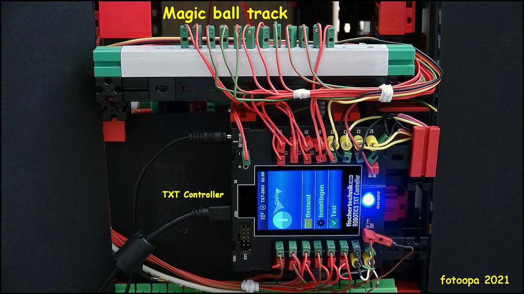
No, Only the regular standard TXT Controller is used. No additional external devives, no I2C. So you can use it with any type of controller, even Arduino or something similar that has the same amount of inputs and outputs as the TXT.
I did 3D print some parts on a limited basis because it makes it easier with the construction that way.
Soon I will share the detail photos. I still need to take some shots. Also the Robopro program which is now very simple needs to be further elaborated. Especially on points of powerup, synchronization and emergency stop states. This afternoon I will not be there, it will be for the next few days.
What I use now are:
8 controlled motors, 6 encoder versions, an XS motor and an XM motor.
12 controlled LEDs.
6 FT switches
2 Hall detectors.
1 optical detector.
The total high is 870 mm.
The width is 600 mm.
Sound of the TXT.
The general rule of construction is stability and reliability. Little tolerance is allowed for holding the balls during the up and down movements. Especially because of the height, you have to add extra reinforcements to keep everything stable. When the balls begin to tumble down unwanted, it becomes a nightmare.
So, soon there will be new images.
Frans.
Re: The magic ball track.
I have uploaded some photos.
HD on Flickr: https://www.flickr.com/photos/fotoopa_hs/51452430712
This is a frame from the video recording of the ball feeder. You can see here how a ball is recorded and transmitted. The feeder is powered by an XS_motor. It rotates one full revolution each time. The end position is given by a 2mm neodym magnet and a hall detector type AH3144E.
HD on Flickr: https://www.flickr.com/photos/fotoopa_hs/51453392173
The TXT Controller controls the magic bullet track here. All inputs and outputs have been used. The I2C was not used here. Because so many GND connections were needed, I made an expander block that can hold up to 15 GND connections. The TXT can work in both online and offline mode.
Ball track descent module. The chain has 328 shackles, 8x41. There are 8 magnet holders on the chain. The magnets are neo dym D5x5mm. The distance between the magnets is 195mm. The magnets are also used to control the Hal detector. Thus, the XM motor rotates over a length of 195mm each time.
HD on Flickr: https://www.flickr.com/photos/fotoopa_hs/51453381231
HD on Flickr: https://www.flickr.com/photos/fotoopa_hs/51452617527
HD on Flickr: https://www.flickr.com/photos/fotoopa_hs/51452617477
Frans.
Re: The magic ball track.
Full Robopro program of the magic bullet track. As you can see 8 tasks running in the program.
UHD picture on Flickr: https://www.flickr.com/photos/fotoopa_hs/51454572258
Frans.
UHD picture on Flickr: https://www.flickr.com/photos/fotoopa_hs/51454572258
Frans.
- PHabermehl
- Beiträge: 2434
- Registriert: 20 Dez 2014, 22:59
- Wohnort: Bad Hersfeld
Re: The magic ball track.
It's a kind of magic. Wonderful. Although logically it must be magnetism, while watching it I thought, please don't show the back side, just let's keep believing in magic. Sooo nice to watch.
Kind regards
Peter
Kind regards
Peter
- Dirk Fox
- ft:pedia-Herausgeber
- Beiträge: 1833
- Registriert: 01 Nov 2010, 00:49
- Wohnort: Karlsruhe
- Kontaktdaten:
Re: The magic ball track.
A wonderful idea and a fantastic model ...
And instead of the hall sensor, a reed contact could be used too, right?
Regards,
Dirk
And instead of the hall sensor, a reed contact could be used too, right?
Regards,
Dirk
- H.A.R.R.Y.
- Beiträge: 1083
- Registriert: 01 Okt 2012, 08:38
- Wohnort: Westpfalz
Re: The magic ball track.
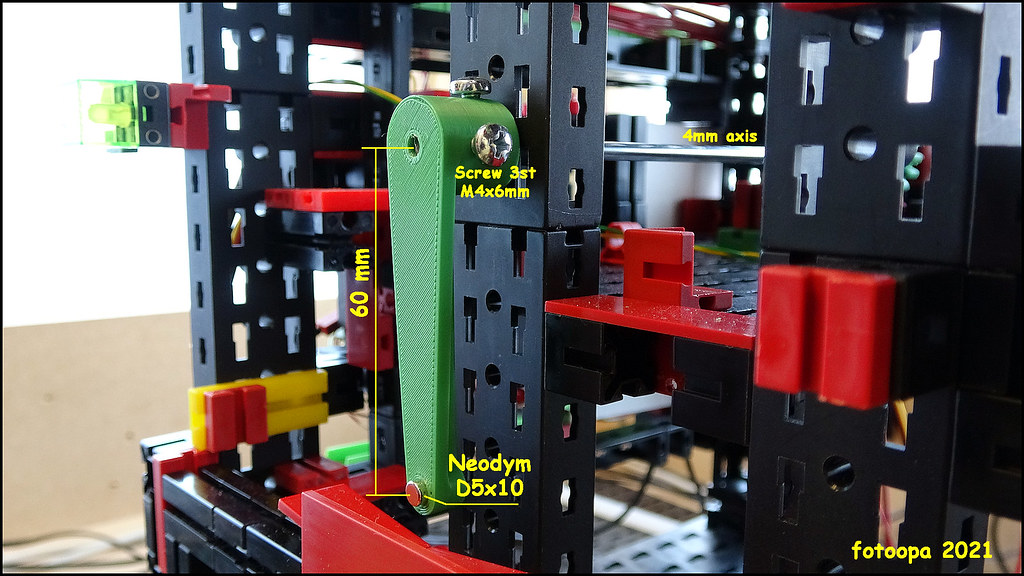
In theory sure, but you might need some additional measures against contact bouncing. Hall (or GMR) is less prone to such effects.
Regards
H.A.R.R.Y.
[42] SURVIVE - or die trying
Re: The magic ball track.
You're right. During the making of the video, the intention was already to show no direct solution. It had to appear magical. Pictures I did give. I would also give other pictures where the front plate is taken away so you see the whole construction. But I'm not going to make a video of it.PHabermehl hat geschrieben: ↑12 Sep 2021, 22:07It's a kind of magic. Wonderful. Although logically it must be magnetism, while watching it I thought, please don't show the back side, just let's keep believing in magic. Sooo nice to watch.
Peter
Yes that would work too. Even if some more vibrations occur it wouldn't be a problem. The program here only responds to the first edge. The other hall sensor that detects the ball is practical though. If there are no more balls the XS motor should stop after a few attempts. You could also give a message on the screen. By the way, the program is still very preliminary. There is still a lot of room for improvement in terms of safety, synchronization, powerup, emergency stop, etc.
Some calculations for the chain are also needed. The timing on descent must be correct. The chain must be stationary when the next ball is coming. Otherwise the ball flies down because there is no magnet to stop it.
I also had to work for a long time to get a stable setup. Placing blocks up to 850mm high and keeping them stable is not always that easy. 0.5mm move of the magnet arms and the magnet has insufficient holding strength. A stronger magnet does not work either because then the friction on the swivel arm is too great. The magnets in the swivel arms are neodym D5x10mm.
Frans
Re: The magic ball track.
A few extra pictures:
Lever with neodym magnet.
HD picture on Flickr: https://www.flickr.com/photos/fotoopa_hs/51462540032
Expander for 15 GND connections. An alu tube of 15x15x1.5mm was used. 15 holes of 2.5mm were drilled at a distance of 7.5mm:
HD picture on Flickr: https://www.flickr.com/photos/fotoopa_hs/51464249425
Drive of the lever with magnet. An encoder motor is used for this purpose. The transmission is via a worm screw and gear with a reduction of 1/15. A camshaft with FT switch determines the end point of rotation.
HD picture on Flickr: https://www.flickr.com/photos/fotoopa_hs/51463549478
Frans.