To program the De0 Nano Soc board for good motor control, I first examined the motor control of FT. For this I made a setup with 2 motors so I can also test them in synchronous mode with FT.

HD pictire Flickr:
https://www.flickr.com/photos/fotoopa_hs/50629423357

HD pictire Flickr:
https://www.flickr.com/photos/fotoopa_hs/50628581528
HD pictire Flickr:
https://www.flickr.com/photos/fotoopa_hs/50629423432
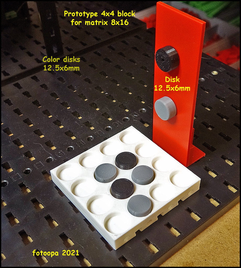
I adjusted the motor torque shaft for the 4mm steel version so there is less backlash. Also the gearing on the chain module is a 3D print version with less backlash. Motor2 contains a weight suspended on a wire as a load. This makes the load asymmetric between up and down movements. Especially in the test mode with synchronous distance of 2 motors, this is a great challenge to obtain good control. I have to admit, Fischer Technik is doing very well in these circumstances. It is not error-free but still satisfactory.
I made a lot of tests and recordings to be able to make a good analysis afterwards.My new Picoscope 2406B does a great job. The very deep buffer storage allows for long shots with relatively small sample periods.
So the recording time is in function of the sample period:
120 ns --> 1 sec
417 ns -->10 sec
800 ns --> 20 sec
2 usec --> 50 sec
4 usec --> 100 sec
For most measurements I use recording times from 2 sec to 50 sec.
Now some recordings in detail:

UHD pictire Flickr:
https://www.flickr.com/photos/fotoopa_hs/50628275877
Attention these recordings are in UHD format to retain details
Description:
Control of 2 motors via the TXT Controller in synchronous distance mode. Motor 2 has an extra load of 0.5kg while motor 1 is an ordinary chain drive. Motor speed is set to V7. The purpose here is to see how the TXT can control both motors with very small errors. You can see in the diagram detail on the right that the PWM signal of motor 2 is almost at max while motor 1 is limited steered. The mutual error of single pulses is at rising motion quite small, 1 to 2 pulses. Left above you see a detail of both motor positions. For this you need to set the zoom factor at the scope very high. Right on the picture you have a table that shows the last position values and the corresponding times.
The complete data of the Picoscope can be saved to make multiple analyses afterwards, look at details, times to measure brake zone, etc.. These measurements will contribute to support my engine control by the FPGA. This data will be available later on. Currently 12 motor drivers are already in the FPGA. This can be extended to 24 or 30 motors all with quadrature decoders and control.

UHD pictire Flickr:
https://www.flickr.com/photos/fotoopa_hs/50628275897
Description:
Here is a detail of the synchronous control of 2 motors by the TXT. The direction here is descending. Motor2 has a negative load of 0.5kg which pushes down. Motor2 has to send less PWM than motor1 to stay synchronous.
A PWM period contains 3 phases. First we see a brake condition that is relatively short. This is followed by a tristate phase. In this tristate phase you see the EMK of the motor. The third phase is the sending out of the motor. A PWM period is 4785 us. The FPGA sends the position of both motors with every decoder change. Detail of this is shown in the table on the right.

UHD pictire Flickr:
https://www.flickr.com/photos/fotoopa_hs/50628275902
Description:
Overview of controlling 2 motors in synchronous distance mode by the TXT. Motor2 with the red line has a negative load of 0.5kg. Motor1 should get much more power because of this and you can see that on CH C which is almost fully driven. Perfect synchronous with uneven load results in a small error during the whole trajectory. At the end of the trajectory motor2 overshoots a bit more because of the negative load. The error is 3 pulses while motor1 is stuck at 1 pulse from the end. The table on the right shows the last postition values. There you see perfectly how the two pos counters count down. For each pos change the time is also shown. You can also measure the speed of the motor.
The small window gives a detail of the forwarding of the position values. They are here on 112 and 109 a mutual error of 3 pulses. Also the times of position change can be read perfectly

UHD pictire Flickr:
https://www.flickr.com/photos/fotoopa_hs/50627430413
Description:
Here is a detail of the brake zone of the engine2. On the 3rd channel the decoder of the FT motor is added here. This gives an even better insight in how the TXT controls the whole thing. A started PWM section is never interrupted. If the state of the position changes at the beginning of a PWM period, the TXT will only react in the next PWM period. Around time 703.8ms you see the integration of the PWM signal. After each PWM period, the output is slightly wider. Slightly before time 739.5 you see that the FT encoder gives a rising edge. The controller adjusts the integration to a lower value and then back up again. Slightly before 757.4 an encoder pulse comes in again, causing the TXT to stop as this is the desired position 200. My spi readout is a bit later, I don't react on the FT encoder but on my quadrature encoder and they are not stark connected. In front of the quadrature encoder there is a gear reduction of the motor.
Between the values of the position you see that more time passes as you approach the end position. The TXT has just slowed down a bit too much ( pos 198 ) so it needs some extra time to reach the last 2 pulses.
On the right the table of the last part of the trajectory with the times

UHD pictire Flickr:
https://www.flickr.com/photos/fotoopa_hs/50627301458
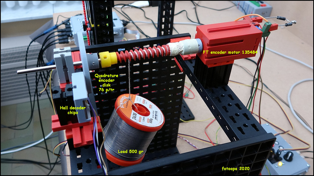
Description:
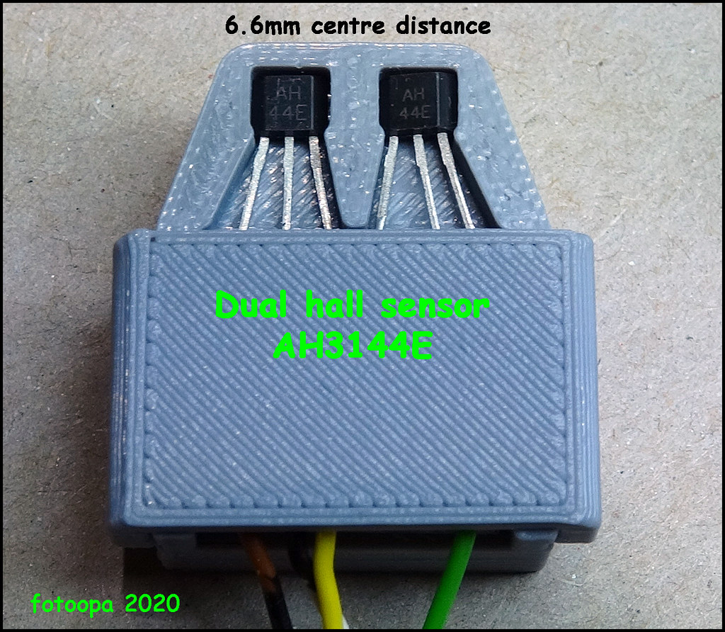
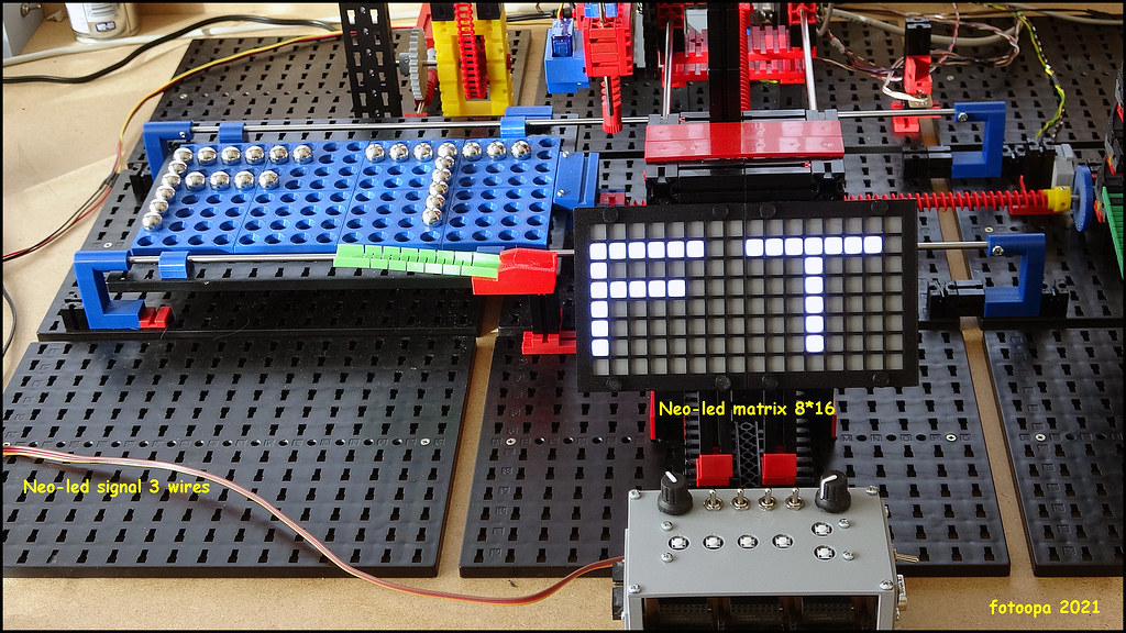
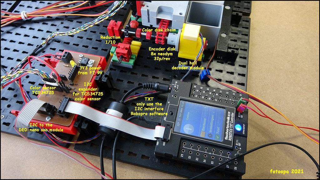
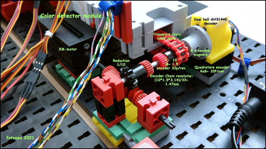
This is a setup to see the FT motor control of the TXT. There are 2 motors FT 135484 used, each with a hall decoder signal. The motors are controlled via RoboPro on the PC and the TXT controller. So there is the possibility to control both motors separately but also to let them work together in synchronous mode. The motor decoder signals are on the C1 and the C2 inputs of the TXT. I also connected them simultaneously to my SPI box which is connected to the FPGA. There are also 2x2 decoder signals connected to the SPI box from additional quadrature decoders. The decoder disks are placed directly on the output motor shaft and give 76 p/tr. The internal decoder of the FT motor gives 76.1719 p/tr.
The SPI I/O box is connected to the FPGA that maintains the position of both motors. These values can be read at any time by the TXT via I2C.
For the measurements the Picoscope 2406B is used with 4 channels, 2GS and a deep buffer memory of 32 Mb. This allows very long recording records to be made. At a sample interval of 2us, recordings can be made up to 100 sec on the 4 channels. I use 2 channels for the analog measurement of the engines. Here are on each motor connection 2 resistors of 68 ohms placed and its center point goes to the scope. So you always have positive signals independent of the motor direction. You measure half the motor voltage versus ground.
The position of both motors, tracked in the FPGA, is at every position change serially sent to the scope. Because I also need an ena signal, the clk + ena are brought together via 3 resistors. This way I save a channel on the scope. The data transfer time for a motor position is 87 usec. Compared to the PWM period of 4785 us you should not miss any position change.
At the max speed of the motor you have about 315 tr/min which gives an encoder pulse every 2500 usec.
The PicoScope can make an export of all these motor position values to put them in tables afterwards and create a diagram. This way you can see the progress of the motor movement as a function of time, deviations, positioning times etc.. With synchronous motor control of 2 motors you also see the mutual deviation.
Sorry for this rather long post. I also have recordings and methods of how I control the motors through the FPGA. This data will be discussed a bit later.
Frans.