Design stepper module for TXT Controller I2C
Verfasst: 08 Mai 2019, 17:43
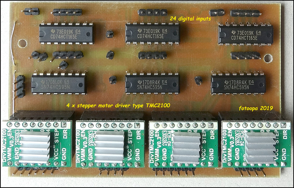
Design for a stepper motor drive.
The stepper motor drive uses the TMC2100 modules from an old 3D printer (FlashForge Finder). I got this gift from a Fischertechnik forum member. The modules are controlled via a spi connection with my FPGA controller. The FPGA is connected to the Fischertechniek TXT Controller via an I2C line. The TMC2100 modules are in a fixed mode of the 3D printer, there is micro stepping used with 16 fine steps per step. Through the SPI connection I can send the ena, DIR, STEP, CFG0 and CFG4 pin. Because the modules are configured in 16 microsteps, the step pulses can be provided quite quickly. Therefore I controlled the SPI driver from a 4MHz clock so that only 13.5 usec is needed to scan all 24 inputs and outputs. This is much faster than the max step speed needed for the stepper.
The SPI goes to the FPGA chip. This is now programmed as a large I2C chip for the user. Besides this stepper driver there are also modules written for 16 motors, 72 inputs, 36 outputs, and 32 servo motors. All inputs can handle fairly fast pulses especially for quadrature encoders. The motors can run in 5 different modes and operate autonomously. The external I2C user only needs to send a few commands. Timing is no problem at all because the FPGA works much faster than the fastest micro controller. There are almost 1000 bytes of registers provided to support all functions. On the Fischertechnik side I have written a full lib to support all these functions. Through the Robopro software you can now write a program in a few minutes to the motors, servo steppers controls, reads inputs, status reads output line controls. I will give you more information about this later, but this data is so extensive that writing the manual takes a lot of time.
Pictures avaible at Flickr: https://www.flickr.com/photos/fotoopa_hs
A few details here:

link original: https://www.flickr.com/photos/fotoopa_hs/32860704417

link original: https://www.flickr.com/photos/fotoopa_hs/33927219378

link original: https://www.flickr.com/photos/fotoopa_hs/47014927034
link original: https://www.flickr.com/photos/fotoopa_hs/33927219258
youtube video: http://youtu.be/0HRdaIm48Q0
More information about my FPGA as a large I2C chip will follow later in a separate topic.
Everything has been tested, all libs for the Robopro TXT Controller are written. Only the complete doc needs to be made up. The principle is that you put a separate (micro)controller on your TXT via the I2C and that all functions are in the Microcontroller. No more software needs to be adapted for this. The microcontroller no longer needs to be reprogrammed. For users who do not use software C or other languages, you can do everything with the Robopro software. You only have to write your program on the TXT. This is very fast and also the execution is very fast because all motors, servo, steppers are controlled realtime completely autonomously outside the TXT.
Frans.
The stepper motor drive uses the TMC2100 modules from an old 3D printer (FlashForge Finder). I got this gift from a Fischertechnik forum member. The modules are controlled via a spi connection with my FPGA controller. The FPGA is connected to the Fischertechniek TXT Controller via an I2C line. The TMC2100 modules are in a fixed mode of the 3D printer, there is micro stepping used with 16 fine steps per step. Through the SPI connection I can send the ena, DIR, STEP, CFG0 and CFG4 pin. Because the modules are configured in 16 microsteps, the step pulses can be provided quite quickly. Therefore I controlled the SPI driver from a 4MHz clock so that only 13.5 usec is needed to scan all 24 inputs and outputs. This is much faster than the max step speed needed for the stepper.
The SPI goes to the FPGA chip. This is now programmed as a large I2C chip for the user. Besides this stepper driver there are also modules written for 16 motors, 72 inputs, 36 outputs, and 32 servo motors. All inputs can handle fairly fast pulses especially for quadrature encoders. The motors can run in 5 different modes and operate autonomously. The external I2C user only needs to send a few commands. Timing is no problem at all because the FPGA works much faster than the fastest micro controller. There are almost 1000 bytes of registers provided to support all functions. On the Fischertechnik side I have written a full lib to support all these functions. Through the Robopro software you can now write a program in a few minutes to the motors, servo steppers controls, reads inputs, status reads output line controls. I will give you more information about this later, but this data is so extensive that writing the manual takes a lot of time.
Pictures avaible at Flickr: https://www.flickr.com/photos/fotoopa_hs
A few details here:
link original: https://www.flickr.com/photos/fotoopa_hs/32860704417
link original: https://www.flickr.com/photos/fotoopa_hs/33927219378
link original: https://www.flickr.com/photos/fotoopa_hs/47014927034
link original: https://www.flickr.com/photos/fotoopa_hs/33927219258
youtube video: http://youtu.be/0HRdaIm48Q0
More information about my FPGA as a large I2C chip will follow later in a separate topic.
Everything has been tested, all libs for the Robopro TXT Controller are written. Only the complete doc needs to be made up. The principle is that you put a separate (micro)controller on your TXT via the I2C and that all functions are in the Microcontroller. No more software needs to be adapted for this. The microcontroller no longer needs to be reprogrammed. For users who do not use software C or other languages, you can do everything with the Robopro software. You only have to write your program on the TXT. This is very fast and also the execution is very fast because all motors, servo, steppers are controlled realtime completely autonomously outside the TXT.
Frans.