Development super "kugelbahn"

fischertechnik in General
Forumsregeln
Bitte beachte die Forumsregeln!
Benutzeravatar
The Rob
Moderator
Beiträge: 968
Registriert: 03 Dez 2015, 12:54

Re: Development super "kugelbahn"

Beitrag von The Rob » 11 Feb 2018, 22:38

Also selbst entwerfen in der Größe die im Kasten vorhanden ist, ist immer schwierig. Irgendwelche Teile fehlen dann.
Besser geht es, entweder eine kleinere Bahn aufzubauen und da die übrigen Teile nach Laune einzusetzen.
Oder einen zweiten Kasten nehmen und bei der größten Bahn einfach weitere Abzweigungen dazu.
Oder den Turmaufbau erhöhen, indem man einfach noch eine Etage draufsetzt. Da muss dann nur die Kette verlängert werden und schon hat man Raum, wo man mehr einbauen kann.
Es gibt das Dynamic Tuningset und dieses Jahr kommen noch jede Menge anderer Erweiterungskästen raus. Die sind dafür prädestiniert.
Auf jeden Fall Respekt davor, wenn du solche Sachen machst, obwohl sie dir schwerfallen. :D

fotoopa
Beiträge: 312
Registriert: 05 Okt 2017, 11:44
Wohnort: Belgie
Kontaktdaten:

Re: Development super "kugelbahn"

Beitrag von fotoopa » 12 Feb 2018, 19:02

The Rob hat geschrieben:Es gibt das Dynamic Tuningset und dieses Jahr kommen noch jede Menge anderer Erweiterungskästen raus. Die sind dafür prädestiniert
I use 4 of these 533873 dynamic tunning set sets, they are a very good addition for a low price.

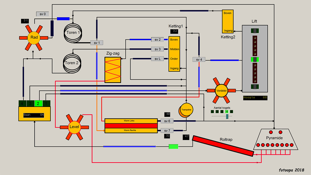
A small update of my super "kugelbahn".
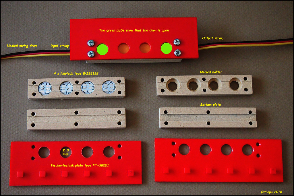
Neo LED construction with MDF wood board and Fischertechnik plate FT-38251.

Bild

Link to the Original picture:
https://www.flickr.com/photos/fotoopa_hs/39329122335

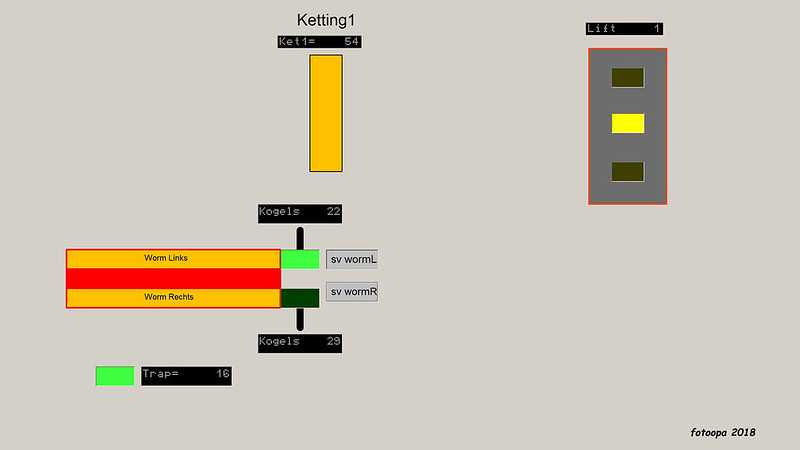
The Neoleds are placed in a block so that they can be connected to each other with a bare solder wire. You do not need a PCB. The 3-pin connector is clamped between the 2 wooden pieces and attached to the Fischertechnik plate FT-38251. Here 4 LEDs are placed in a row. The 2 outer LEDs indicate in green that the lift door is open. When the door is closed, the 2 central LEDs are shown in red. All Neoleds are in a string and each LED can have its own colour (24bit RGB). For the string control you only need 5V and only 1 drive pin of the controller. All LEDs fit in a string, I have 120 pieces available.

My lift of the trajectory has 3 double moving doors, which shows the status. Between the LEDs and Fischer Plate there is a white sheet of paper for light distribution + an orange colour filter to reduce the blue light somewhat.
As soon as the 3 LED indicators are mounted, I can start to make a video. Then everything will be even clearer. The various routes that are possible will also be shown regularly in a video. But this requires some video editing work!
Answers may also be the German language, I do read it.

Frans.

Benutzeravatar
The Rob
Moderator
Beiträge: 968
Registriert: 03 Dez 2015, 12:54

Re: Development super "kugelbahn"

Beitrag von The Rob » 13 Feb 2018, 01:29

Hi Frans,

sorry for abusing your thread for discussing sets.
Glad to see that the latest language discussion didn't discourage you.
Are you using two LED (two green and two red) for each door for design reasons, or technical?

fotoopa
Beiträge: 312
Registriert: 05 Okt 2017, 11:44
Wohnort: Belgie
Kontaktdaten:

Re: Development super "kugelbahn"

Beitrag von fotoopa » 13 Feb 2018, 08:49

The Rob hat geschrieben:Are you using two LED (two green and two red) for each door for design reasons, or technical?
Just for design reason. Technically it takes a bit more work, 4 leds have to be changed now when the door moves. The LEDs are on the 15 mm pitch of fischer block. By taking 4 LEDs, the active LEDs are in the centre of the door position. It's much more beautiful and it feels logical as well.

The color of the LEDs have a simple program structure into my FPGA. Each LED can contain 4 predefined 24 bit colors. I use a dual ported ram from the FPGA for this purpose. In addition, each led has a 4 bit mode. The 2 lowest bits select one of the 4 predefined colors, the 2 highest bits have a enable and flashing function. To control a LED, only the 4-bit mode needs to be changed, not the 24 bit color value. The output task reads this 4 bit mode and uses the correct color and function per LED. The program is designed for 128 LEDs. The timing of other program components are not affected by this. Neoleds need very strict timing.

fotoopa
Beiträge: 312
Registriert: 05 Okt 2017, 11:44
Wohnort: Belgie
Kontaktdaten:

Re: Development super "kugelbahn"

Beitrag von fotoopa » 13 Feb 2018, 17:41

The neo LEDs are now mounted on the elevator together with the 7 segment display at the top that indicates the level and also the direction in ascending or descending. The colours of the LEDs are in reality much more beautiful and accurate. On a photo or video, this can almost never be reproduced correctly. The proportion of blue in the LEDs remains much too high and gives a bad color reproduction along with saturation. The lift has 8 servos, 12 neo leds, one XM-motor, one Rotary encoder, one hall end switch and a dual 7 segment display. Everything can also be controlled via the IR remote control.
Here is a picture of the results:

Bild

A direct link to the Original picture:
https://www.flickr.com/photos/fotoopa_hs/25374716517

Now I still need to update some FPGA software to let the elevator work completely autonomously with the doors, the neo led status and the 7 segment display. Most of the functions are already working, however, so that should not be a problem.

Frans.

Benutzeravatar
MasterOfGizmo
Beiträge: 2720
Registriert: 30 Nov 2014, 07:44

Re: Development super "kugelbahn"

Beitrag von MasterOfGizmo » 13 Feb 2018, 18:52

Why do you use an FPGA for this? Looks like an Arduino would also easily be able to do the job. Not that i have anything against FPGAs. But this sounds like a total overkilll ...
Arduino für fischertechnik: ftDuino http://ftduino.de, ftDuino32 http://ftduino.de/32

Benutzeravatar
PHabermehl
Beiträge: 2427
Registriert: 20 Dez 2014, 22:59
Wohnort: Bad Hersfeld

Re: Development super "kugelbahn"

Beitrag von PHabermehl » 13 Feb 2018, 19:06

Really a stunning project, I'm a little jealous.

Kind regards
Peter
https://www.MINTronics.de -- der ftDuino & TX-Pi Shop!

viele Grüße
Peter

fotoopa
Beiträge: 312
Registriert: 05 Okt 2017, 11:44
Wohnort: Belgie
Kontaktdaten:

Re: Development super "kugelbahn"

Beitrag von fotoopa » 13 Feb 2018, 19:08

MasterOfGizmo hat geschrieben:Why do you use an FPGA for this? Looks like an Arduino would also easily be able to do the job. Not that i have anything against FPGAs. But this sounds like a total overkilll ...
This is only one module of the hole super "Kugelbahn" I need 100 inputs/outputs on my FPGA. I have used the the ATxmega-256A3U but it is also far too small. An FPGA gives you all the freedom you need for your input and output signals and functions. This makes the layout very simple and you don't have any time problems, not even for the Neo leds. Cost price is little different and negligible compared to the entire project. Few people use FPGA because they have no experience with it. My FPGA currently uses 18% of its cells.

It will become much clearer if some video recordings are also ready.

Benutzeravatar
gamma
Beiträge: 27
Registriert: 04 Jan 2013, 17:38
Wohnort: Deutschland

Re: Development super "kugelbahn"

Beitrag von gamma » 13 Feb 2018, 23:00

Der Parcours 1 gefällt mir ganz gut. Falls man ein Teil falsch verbaut funktioniert sie nicht richtig.
Schade dass die Kugeln kein Muster haben und für die 8 Kugeln nur 4 Magnethalter dabei sind.
Hast du alle 3 gebaut und welche gefällt dir am besten?
Macht das Abbauen auch Spaß?

Hier ein Video: https://youtu.be/IjSBs6At-gA
Auf n-tv eine fischer-Doku um 2:30
The Rob hat geschrieben:Also selbst entwerfen in der Größe die im Kasten vorhanden ist, ist immer schwierig. Irgendwelche Teile fehlen dann.
Besser geht es, entweder eine kleinere Bahn aufzubauen und da die übrigen Teile nach Laune einzusetzen.
Oder einen zweiten Kasten nehmen und bei der größten Bahn einfach weitere Abzweigungen dazu.
Oder den Turmaufbau erhöhen, indem man einfach noch eine Etage draufsetzt. Da muss dann nur die Kette verlängert werden und schon hat man Raum, wo man mehr einbauen kann.
Es gibt das Dynamic Tuningset und dieses Jahr kommen noch jede Menge anderer Erweiterungskästen raus. Die sind dafür prädestiniert.
Auf jeden Fall Respekt davor, wenn du solche Sachen machst, obwohl sie dir schwerfallen. :D

Benutzeravatar
gamma
Beiträge: 27
Registriert: 04 Jan 2013, 17:38
Wohnort: Deutschland

Re: Development super "kugelbahn"

Beitrag von gamma » 16 Feb 2018, 14:29

Das Video gefällt mir nicht so gut.
Das neue ist etwas besser: fischertechnik Kugelbahn L2 mit SS Lampen und Elektromagnet

Der Elektromagnet funktioniert mit den Kugeln.

Benutzeravatar
gamma
Beiträge: 27
Registriert: 04 Jan 2013, 17:38
Wohnort: Deutschland

Re: Development super "kugelbahn"

Beitrag von gamma » 22 Feb 2018, 19:30

Die Batterie ist irgendwie zu schwach.
Der alte ft-Transformator liefert nur 6,8 Volt.
Ich habe jetzt dieses Netzteil. Passt das?

https://ft.gpsu.de/

Kilian
Beiträge: 249
Registriert: 06 Nov 2014, 14:16

Re: Development super "kugelbahn"

Beitrag von Kilian » 23 Feb 2018, 07:58

Ja, passt. Ganz praktisch ist, dass man die - zur Schonung alter Birnchen - auch mal auf 6V oder andererseits für ordentlich Power auch auf 12V stellen kann. Was nicht so gut geht, ist z.B. mehrere Birnchen via Blinkelektronik und gleichzeitig einen Motor betreiben. Da haben die einfach zu wenig Leistung und im Takt der Birnchen schwankt dann leicht die Motordrehzahl (klingt halt doof). Dafür dann entweder ein Netzteil mit 4A oder mehrere kleine.
Beste Grüße
Kilian

fotoopa
Beiträge: 312
Registriert: 05 Okt 2017, 11:44
Wohnort: Belgie
Kontaktdaten:

Re: Development super "kugelbahn"

Beitrag von fotoopa » 15 Mär 2018, 16:52

I have just put the first video of my "superkogelbaan" online. It mainly shows the details of the different modules used. You can see details of the control sensors. It is a first real video shooting test. I have tried as much as possible to display the overview of the modules. Towards the end there is also a short overview of the hardware controller. This is rather limited and will be shown in more detail in another video later on. The video is in full HD 1920x1080 50p.

https://youtu.be/yZnnx5vvjQU

I hope this first video will help you to understand how the "superkogelbaan" was built. At the end of the video you can see a number of drawings of the trajectories. You can select these routes with just a few buttons. I am now working on a complete book with drawings for the children. Then they only have to choose a drawing to make the right settings. A number of pre-programmed tracks are now also created in the FPGA controller. These can be selected by the children to execute. It can't be easier to use. But they can still change the routes during the implementation. They can also change this via the IR control. I have 43 keys on the IR control of which about 30 touches are already in use. When a new key is needed, the code can be read from the LCD display in real time. Position of the motors, sensors, servos, yes all of them can be read while the balls are travelling along the tracks.

The video shows the colors of the Neoleds completely wrong. In reality the colors are beautiful green and red. This is because the video sensor shows too much blue light and is therefore overexposed.

Frans.

fotoopa
Beiträge: 312
Registriert: 05 Okt 2017, 11:44
Wohnort: Belgie
Kontaktdaten:

Re: Development super "kugelbahn"

Beitrag von fotoopa » 27 Mär 2018, 19:17

New change in the way I operate my super "Kugelbahn". I bought a Fischertechnik controller TXT. I'm going to place this controller on the top layer to control the programs. In fact, this controller doesn't have to work much. All macro functions have already been programmed in the FPGA. Positioning, counting, controlling servos, etc. are all functions for the FPGA. For example, the information of a servo is very limited, it is only on the left or on the right. A servo data info for the Fischer controller only needs to be 1 bit. This gives the TXT controller sufficient information on the state of the servo. I have a number of counters with 2 digit information. They are used to count the number of balls coming along. If I pass this value on as an 8-bit integer, the TXT controller can process this information. All this data I am going to process via the external I2C connection. To do this, I only need to include the driver in the FPGA. I have already connected the TXT controller to my FPGA console:

Bild

Link on my Flickr:
https://www.flickr.com/photos/fotoopa_hs/27180422858

Meanwhile, the ROBOPRO program runs perfectly together with the PC and the USB link with the TXT controller. A small test program allows me to view the I2C communication. This way I see the levels, timing, data, protocol etc. Here is a picture of the programming environment:

Bild
Link on my Flickr:
https://www.flickr.com/photos/fotoopa_hs/26180951307

Everything looks good, I can now also evaluate the load on the I2C line. My FPGA is a 3.3V type connection, I don't need a level converter. I wonder if I still have to provide both signal lines with a pullup resistor. For that I have made an adaptable setup. The pulup in the TXT controller probably turns out to be around 3K3. I have also added 3K3 myself. Then the positive edge of the signals is much better. However, if my FPGA is off, the line voltage becomes 1.75V. When connected in this way, the TXT controller no longer works because it sees the bus as occupied. This is correct. I can still see a lot of details that are important to write my own driver into the FPGA and to correctly adjust the hardware. So, a decent task for the next few days!

Frans.

fotoopa
Beiträge: 312
Registriert: 05 Okt 2017, 11:44
Wohnort: Belgie
Kontaktdaten:

Re: Development super "kugelbahn"

Beitrag von fotoopa » 01 Apr 2018, 17:53

Tests with the Robopro software and the FPGA via I2C are running smoothly. I can read all data from the FPGA and send back commands. I am using the software in online mode. Here's a small example of how things are going:

Bild

Flickr link: https://www.flickr.com/photos/fotoopa_hs/41159025541

Bild

Flickr link: https://www.flickr.com/photos/fotoopa_hs/27287011968

Of course this is only a start, now I can already read out all the data that is needed. I can also send commands to the FPGA. This allows me to develop full programs on the Robopro software. This is very fast and on a full 32 inch UHD screen you have a very good overview. I am now going to draw the trajectory completely on my screen. In a very short time I have such a working system. I only use the I2C interface of the TXT controller and the Robopro software as all control functions are already provided by the FPGA.

On the FPGA:
16 Motors max 1.2A
32 servo outputs (max 64)
128 Neoleds.
Multiple high-speed Rotary encoders, now 5 inuse.
Multiple inputs for all type sensors.
LCD display 4x20 chars.
3 full SPI in-out external lines
I2C line for the TXT controller at 3.3V
4 dual 7 segment displays.

Frans.

fotoopa
Beiträge: 312
Registriert: 05 Okt 2017, 11:44
Wohnort: Belgie
Kontaktdaten:

Re: Development super "kugelbahn"

Beitrag von fotoopa » 04 Apr 2018, 20:53

Robopro program is now ready:

Bild

The full HD version:
https://www.flickr.com/photos/fotoopa_hs/40521956574

The Robopro program is now working and the measured values of the FPGA controller will now appear on the 32 inch screen in real time. The blue lines are software LEDs that are controlled by the program. They indicate the actively selected track. The small black blocks contain counter values. The elevator is at 68m altitude, 47 bullets have been raised along the escalator, the 4way selector is on track 2, there have been 32 bullets along the ketting1 and also the wormL and wormR have been marked. The number of bullets that can be moved into the elevator can be set between 1 and 5 (at the bottom of the "verdeler") and is now set to 4.

The elevator contains 2 x 5 additional software LEDs on the screen. These indicate how far the elevator has come during the ascent and descent.
The Robopro software runs quite fast. There is only 2.6ms CPU time between each data block from the FPGA. Between each I2C access there is 920 usec. Via the I2C, 7 registers of 8 bits each are read from the FPGA and 1 byte of data is written to the FPGA.

Especially the ability to interactively change the screen according to the settings times running the bullets is really super.

Nexttime I will show a realtime video.
Frans

Antworten