Ball detector module 3D print
Verfasst: 05 Nov 2018, 20:29
Ball detector module.
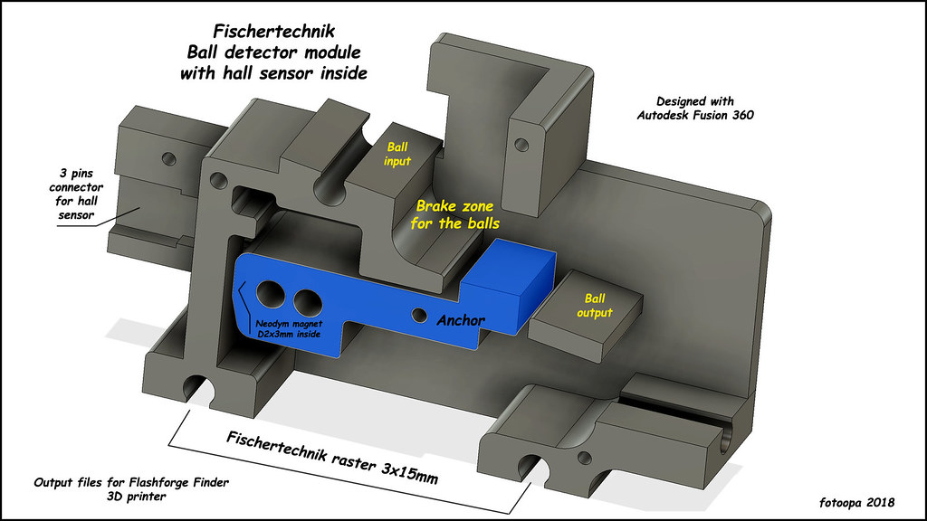
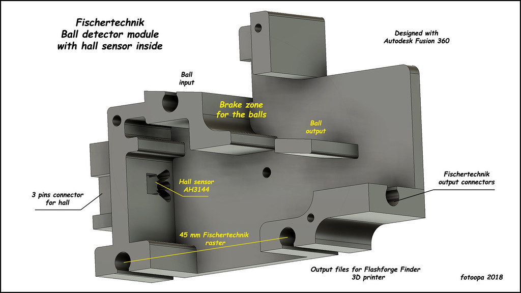
Can be used to count or detect the number of balls. Works with a hall chip built into the module. A small Neodym magnet is built into a rotating anchor. In order to measure a series of balls properly, a brake zone is built in. Without this braking zone the anchor will otherwise not have time to move back. The anchor has 2 extra holes of 4 mm. They can be used to place small steel axles as extra counterweight. However, I have tested it even without these extra weights and it works perfectly. The first hole of 4mm also serves to pull out the small magnet if you have the wrong polarity. I made a reference setup so that I have the correct polarity before pressing the magnet.
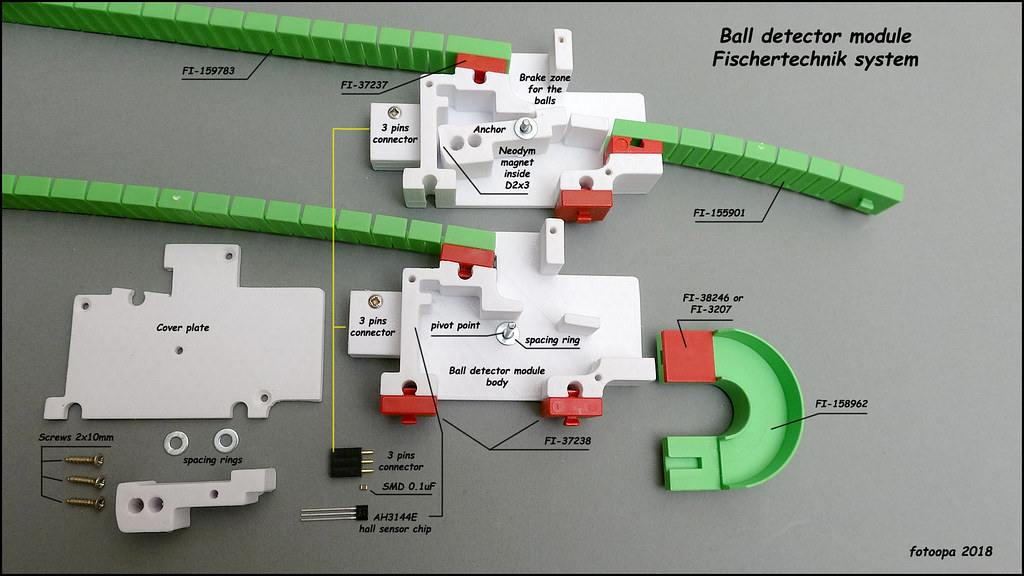
In the module extra height has been kept free to use Fischertechnik blocks. These are indicated on the drawing. Original Fischertechnik parts are always easier to connect with other parts. These extra parts are also shown in the drawing. The output of the module can be made via a straight connection or a 180 degree connection. All necessary blocks are also shown in the drawing.
For the hall connection I use a 3 pin female connetor. The wires of the hall can be easily connected without additional PCB. I swapped the 2 power pins of the hall output to the connector so the connector would have a standard connection: Output, +VCC, GND. This wiring then corresponds to that of a servo connection. The hall has an open collector output so it can easily be used on any kind of interface. Its power supply itself can be between 4V and 24V. The most commonly used voltage is 5V.
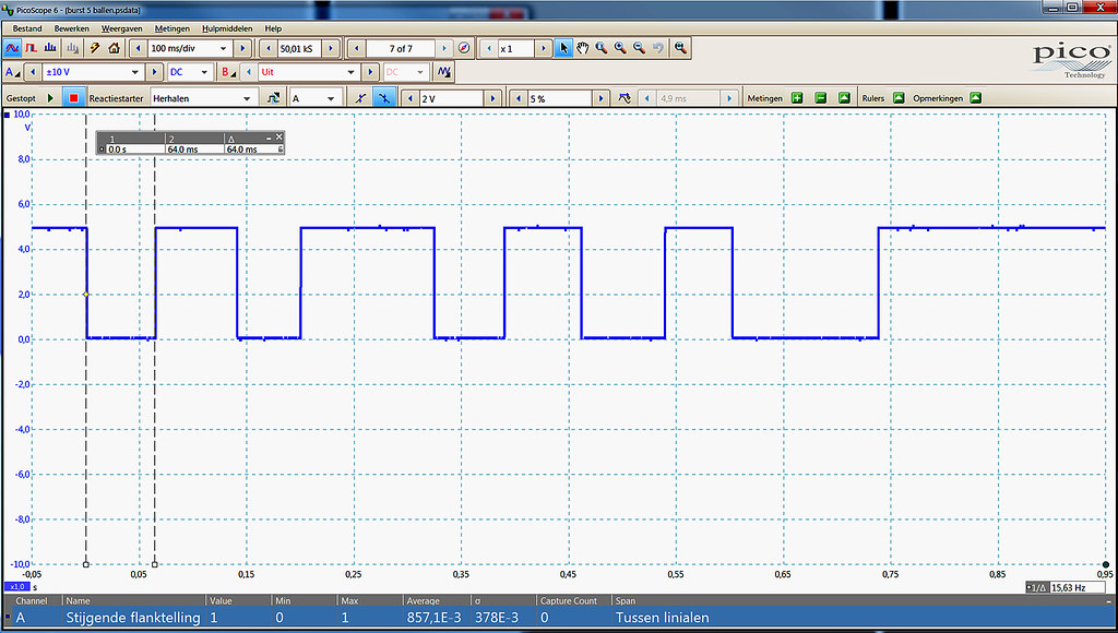
A drawing is also included with the timing results for a burst of 5 balls. You have to take into account that sometimes the speed can be quite high (pulses about 25 msec). You may need to sharpen the brake zone ( adjusts the input so that the ball can just pass) if your controller cannot handle this speed. This is the case for the TXT Controller Fischertechnik. I use my FPGA controller to read the pulses and it never has speed problems.
All parts are printed with the Flachforge Finder 3D printer. The filament used is PLA 1.7mm, 210 degree, Raft and Brim enabled, Infill 25%.
Link to thingiverse: https://www.thingiverse.com/thing:3197799
A few prictures:
HD: https://www.flickr.com/photos/fotoopa_hs/31865671518
HD: https://www.flickr.com/photos/fotoopa_hs/43919471080
HD: https://www.flickr.com/photos/fotoopa_hs/44823074945
HD: https://www.flickr.com/photos/fotoopa_hs/43919471380
Frans.
Can be used to count or detect the number of balls. Works with a hall chip built into the module. A small Neodym magnet is built into a rotating anchor. In order to measure a series of balls properly, a brake zone is built in. Without this braking zone the anchor will otherwise not have time to move back. The anchor has 2 extra holes of 4 mm. They can be used to place small steel axles as extra counterweight. However, I have tested it even without these extra weights and it works perfectly. The first hole of 4mm also serves to pull out the small magnet if you have the wrong polarity. I made a reference setup so that I have the correct polarity before pressing the magnet.
In the module extra height has been kept free to use Fischertechnik blocks. These are indicated on the drawing. Original Fischertechnik parts are always easier to connect with other parts. These extra parts are also shown in the drawing. The output of the module can be made via a straight connection or a 180 degree connection. All necessary blocks are also shown in the drawing.
For the hall connection I use a 3 pin female connetor. The wires of the hall can be easily connected without additional PCB. I swapped the 2 power pins of the hall output to the connector so the connector would have a standard connection: Output, +VCC, GND. This wiring then corresponds to that of a servo connection. The hall has an open collector output so it can easily be used on any kind of interface. Its power supply itself can be between 4V and 24V. The most commonly used voltage is 5V.
A drawing is also included with the timing results for a burst of 5 balls. You have to take into account that sometimes the speed can be quite high (pulses about 25 msec). You may need to sharpen the brake zone ( adjusts the input so that the ball can just pass) if your controller cannot handle this speed. This is the case for the TXT Controller Fischertechnik. I use my FPGA controller to read the pulses and it never has speed problems.
All parts are printed with the Flachforge Finder 3D printer. The filament used is PLA 1.7mm, 210 degree, Raft and Brim enabled, Infill 25%.
Link to thingiverse: https://www.thingiverse.com/thing:3197799
A few prictures:
HD: https://www.flickr.com/photos/fotoopa_hs/31865671518
HD: https://www.flickr.com/photos/fotoopa_hs/43919471080
HD: https://www.flickr.com/photos/fotoopa_hs/44823074945
HD: https://www.flickr.com/photos/fotoopa_hs/43919471380
Frans.