First experiences with 3D printing.
Verfasst: 03 Okt 2018, 17:10
When I recently saw the realisations here on the forum of the members I was immediately super motivated to be able to print 3D myself. I also got a lot of help from the forum member "Bello". I immediately started to look up some general information about 3D printers. However, I had no intention of having to put something together myself, so it had to be a ready-to-install printer. I also didn't want to invest a super high amount of money in something I don't know if I would use it frequently. That the dimensions are then limited and you don't have a heating print bed was the compromise that had to be taken. With the help of "Bello" the decision was quickly taken to buy a Flashforge Finder 3D printer. In a few days I had processed a lot of information, read user manuals, read print problems, filament choices etc. My birthday was coming, just in time to order the printer. It was delivered the day before and the grandchildren could give the gift!
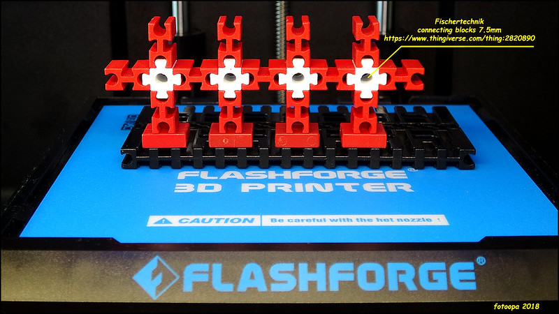
Enough has been said, now the first realisations. My first tests were taken from the dwonload files (Juh) of a 7.5mm connecting block. At the same time I had already drawn a test block in Autodesk Fusion 360 to measure the dimensions and deviations during printing. And yes the first 3D print was coming up, perfect result without a single problem. I had already given those images in the other topic but now I have a further overview.
The first print:
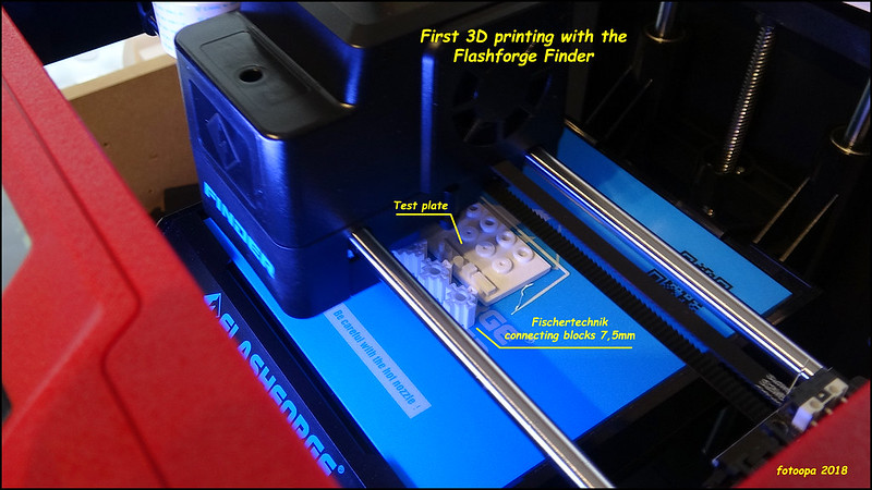
HD picture: https://www.flickr.com/photos/fotoopa_hs/43240783730
HD picture: https://www.flickr.com/photos/fotoopa_hs/44332148714
Meanwhile I have drawn an encoder disk for quadrature encoding. It is equipped with small Neodym magnets of D2x3mm. Also a home point is provided. The encoder disk is also drawn in FS360 and contains an adjustable parameter "nr_mag" to make other disks without renewing the basic drawing.
A print of this can be seen here:
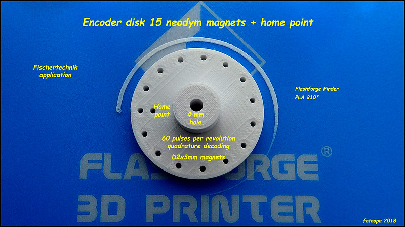
HD version: https://www.flickr.com/photos/fotoopa_hs/31202772688
This picture was taken from the print table.
After the final processing and pressing of the 15 + 1 neodymium magnets this picture:
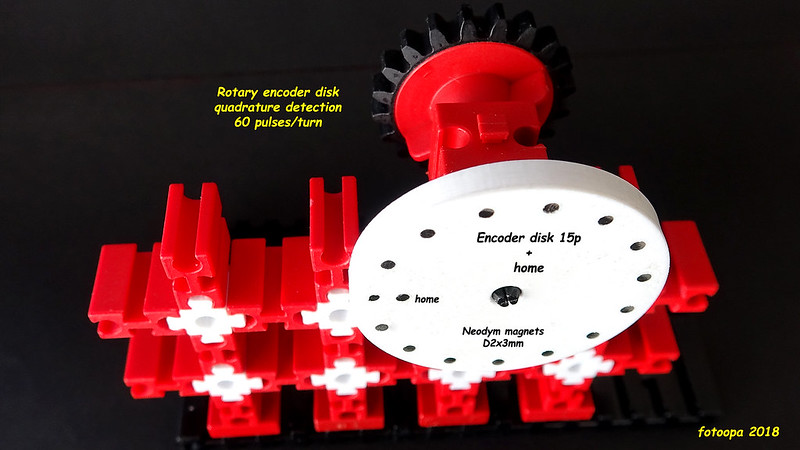
HD version: https://www.flickr.com/photos/fotoopa_hs/44355385824
The neodymium magnets are D2x3mm and are pressed in. First, the holes are drilled with a drill D2.0 mm. During the pressing you have to check the polarity of the magnets. The hall detectors are unipolar versions that I use. The central bore is drilled to size using a d4 mm drill. This gives you a clamp fit. If you want a free fit you have to drill out 4.1mm. Because the holes are already pre-printed, this adjustment can be made by hand. A small vertical drill stand is recommended.
My next assignment is to design several small FT particles for a super ball track that I would realize again. Now I have many more possibilities. My school education was technical engineer mechanics. Afterwards I switched to electronics design to design machine controllers for 26 years. The last years before my retirement I also designed hardware for image recognition with Xrray machines. Hence some experience with optics and lasers.
The next step will be to make my new creations available on Thinkiverse. I just created an account and later on the first results will follow. I am still a novice in all these new matters, There will be a lot of improvements.
Frans.
Enough has been said, now the first realisations. My first tests were taken from the dwonload files (Juh) of a 7.5mm connecting block. At the same time I had already drawn a test block in Autodesk Fusion 360 to measure the dimensions and deviations during printing. And yes the first 3D print was coming up, perfect result without a single problem. I had already given those images in the other topic but now I have a further overview.
The first print:
HD picture: https://www.flickr.com/photos/fotoopa_hs/43240783730
HD picture: https://www.flickr.com/photos/fotoopa_hs/44332148714
Meanwhile I have drawn an encoder disk for quadrature encoding. It is equipped with small Neodym magnets of D2x3mm. Also a home point is provided. The encoder disk is also drawn in FS360 and contains an adjustable parameter "nr_mag" to make other disks without renewing the basic drawing.
A print of this can be seen here:
HD version: https://www.flickr.com/photos/fotoopa_hs/31202772688
This picture was taken from the print table.
After the final processing and pressing of the 15 + 1 neodymium magnets this picture:
HD version: https://www.flickr.com/photos/fotoopa_hs/44355385824
The neodymium magnets are D2x3mm and are pressed in. First, the holes are drilled with a drill D2.0 mm. During the pressing you have to check the polarity of the magnets. The hall detectors are unipolar versions that I use. The central bore is drilled to size using a d4 mm drill. This gives you a clamp fit. If you want a free fit you have to drill out 4.1mm. Because the holes are already pre-printed, this adjustment can be made by hand. A small vertical drill stand is recommended.
My next assignment is to design several small FT particles for a super ball track that I would realize again. Now I have many more possibilities. My school education was technical engineer mechanics. Afterwards I switched to electronics design to design machine controllers for 26 years. The last years before my retirement I also designed hardware for image recognition with Xrray machines. Hence some experience with optics and lasers.
The next step will be to make my new creations available on Thinkiverse. I just created an account and later on the first results will follow. I am still a novice in all these new matters, There will be a lot of improvements.
Frans.